.NET Core and GPIO on the Raspberry PI - LEDs and GPIO
In the previous article, I explored installing and running .NET Core 3.0 on a Raspberry PI running Raspbian. In this article I intend to create a simple console application that will interact with the GPIO and flash an LED.
What is a GPIO?
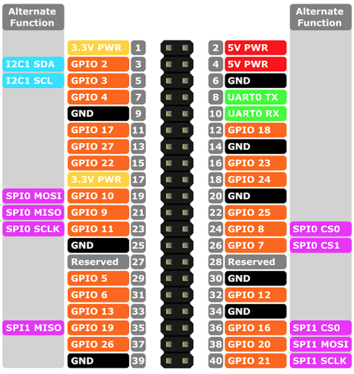
GPIO stands for General Purpose Input Output. A GPIO pin has no predefined purpose - i.e. they are unused by the main device and can be configured as input or output and can be controlled by an application. The Raspberry Pi has two rows of GPIO pins, as well as others.
Output pins are like switches that your app running on the Raspberry Pi can turn on or off - common uses include turning on LEDs, but they can be used for more advanced communication with devices.
Input pins can be turned on and off by external devices such as switches, however they too can be used for more advanced communication with devices, such as receiving information from sensors.
.NET Core IoT Libraries
So how can we interact with the GPIO? Fortunately, there are a set of NuGet packages that do the heavy lifting for us the source is hosted here - https://github.com/dotnet/iot.
To quote the repository:
.NET Core can be used to build applications for IoT devices and scenarios. IoT applications typically interact with sensors, displays and input devices that require the use of GPIO pins, serial ports or similar hardware.
This repository contains the System.Device.Gpio library and implementations for various boards like Raspberry Pi and Hummingboard.
The repository also contains IoT.Device.Bindings, a growing set of community-maintained device bindings for IoT components.
NOTE: This repository is still in experimental stage and all APIs are subject to changes.
This library provides the means to interact with sensors via GPIO, SPI, I2C and PWM. You can checkout the documentation here.
For this article, we will focus on plain vanilla GPIO.
Create a Simple LED Flasher
Let's create a .NET Core Console app that uses GPIO to flash an LED.
-
Connect to your PI via a terminal.
-
Navigate to a directory where you want to create your project folder.
-
To create you project folder, enter the following command:
mkdir SimpleFlasher -
To navigate into the project folder, enter the following command:
cd SimpleFlasher -
To create the initial console application project, enter the following command:
dotnet new consoleAfter a few moments, you will have a simple hello world app.
-
To test the app, enter the following command:
dotnet runAfter a few moments compiling, etc. you will see Hello World!.
-
To add the package references we will be using for the GPIO communication, enter the following commands:
dotnet add package System.Device.Gpio --source https://dotnetfeed.blob.core.windows.net/dotnet-iot/index.json
dotnet add package Iot.Device.Bindings --source https://dotnetfeed.blob.core.windows.net/dotnet-iot/index.json
The SimpleFlasher.csproj file will now look like:
<Project Sdk="Microsoft.NET.Sdk">

<PropertyGroup>
    <OutputType>Exe</OutputType>
    <TargetFramework>netcoreapp3.0</TargetFramework>
</PropertyGroup>

<ItemGroup>
        <PackageReference Include="IoT.Device.Bindings" Version="1.0.0" />
        <PackageReference Include="System.Device.Gpio" Version="1.0.0" />  </ItemGroup>

</Project>
Before we go any further though, let's explore something that will make our development much simpler - VS Code Remote Development.
VS Code Remote Development
To quote the VS Code Remote Development page:
Visual Studio Code Remote Development allows you to use a container, remote machine, or the Windows Subsystem for Linux (WSL) as a full-featured development environment. You can:
- Develop on the same operating system you deploy to or use larger or more specialized hardware.
- Sandbox your development environment to avoid impacting your local machine configuration.
- Make it easy for new contributors to get started and keep everyone on a consistent environment.
- Use tools or runtimes not available on your local OS or manage multiple versions of them.
- Develop your Linux-deployed applications using the Windows Subsystem for Linux.
- Access an existing development environment from multiple machines or locations.
- Debug an application running somewhere else such as a customer site or in the cloud.
We will focus on using the Remote - SSH part of the extension to aid in our development.
-
Open Visual Studio Code and press CTRL + SHIFT + X to open the Extensions pane.
-
To install the Remote Development extension pack, enter Remote Development and click Install.
Note: The extension has the extension identifier
ms-vscode-remote.vscode-remote-extensionpackso you can be sure you are installing the correct one. -
To open the command pane, press F1 and enter Remote-SSH: Connect to host
-
When prompted to Select configured SSH host or enter user@host, enter pi@.
A new Visual Studio Code window will open and you will be prompted to enter the user password... do so.
You will see a notification that informs you the SSH host is being configured.
Once the configuration is complete, Visual Studio Code will be connected to the PI and you can browse the PI filesystem.
-
To open the SimpleFlasher folder, select File > Open Folder and browse to the location you created the project folder. Select SimpleFlasher.
-
Once you choose the folder, you may be prompted for the password again - enter it.
The explorer window will now display the contents of the folder.
-
Open Program.cs.
It will look something like this:
using System; namespace SimpleFlasher { class Program { static void Main(string[] args) { Console.WriteLine("Hello World!"); } } } -
Update the
Console.WriteLine("Hello World!");line toConsole.WriteLine("Hello World - updated from VS Code!");and save the changes. -
To run the app from within Visual Studio Code, press CTRL + SHIFT `
You should see a bash terminal open connected to your PI with the current directory set to the location you have open in the file explorer.
-
To run your revised app, enter
dotnet run.
Success! We now have the convenience of editing our code in Visual Studio Code.
Simple Flashing Sample
We'll now update our application to interact with the GPIO bus and flash an LED... I know, global electronic domination follows... BTW, I bought a kit from Freenove via Amazon that has a huge variety of components: Freenove Ultimate Starter Kit for Raspberry Pi 4 B 3 B+, 434 Pages Detailed Tutorials, Python C Java, 223 Items, 57 Projects, Learn Electronics and Programming, Solderless Breadboard
-
In Visual Studio Code, replace the contents of the Program.cs file with the following:
using System;
using System.Device.Gpio;
using System.Threading;
using System.Threading.Tasks;

namespace SimpleFlasher {
    class Program {
        static void Main (string[] args) {
            // GPIO 17 which is physical pin 11
            int ledPin1 = 17;
            GpioController controller = new GpioController ();
            // Sets the pin to output mode so we can switch something on
            controller.OpenPin (ledPin1, PinMode.Output);

            int lightTimeInMilliseconds = 1000;
            int dimTimeInMilliseconds = 200;

            while (true) {
                Console.WriteLine ($"LED1 on for {lightTimeInMilliseconds}ms");
                // turn on the LED
                controller.Write (ledPin1, PinValue.Low);
                Thread.Sleep (lightTimeInMilliseconds);
                Console.WriteLine ($"LED1 off for {dimTimeInMilliseconds}ms");
                // turn off the LED
                controller.Write (ledPin1, PinValue.High);
                Thread.Sleep (dimTimeInMilliseconds);
            }
        }
    }
}
Due to the polarity of the wiring for the circuit, pulling a pin low (
PinValue.Low) turns on the LED. -
From the above you can see that using
GpioControlleris pretty straightforward:- You create an instance of
GpioController. - Using the instance, you can open pins and set their modes
- You can then write (or read) values from the pin.
- You create an instance of
-
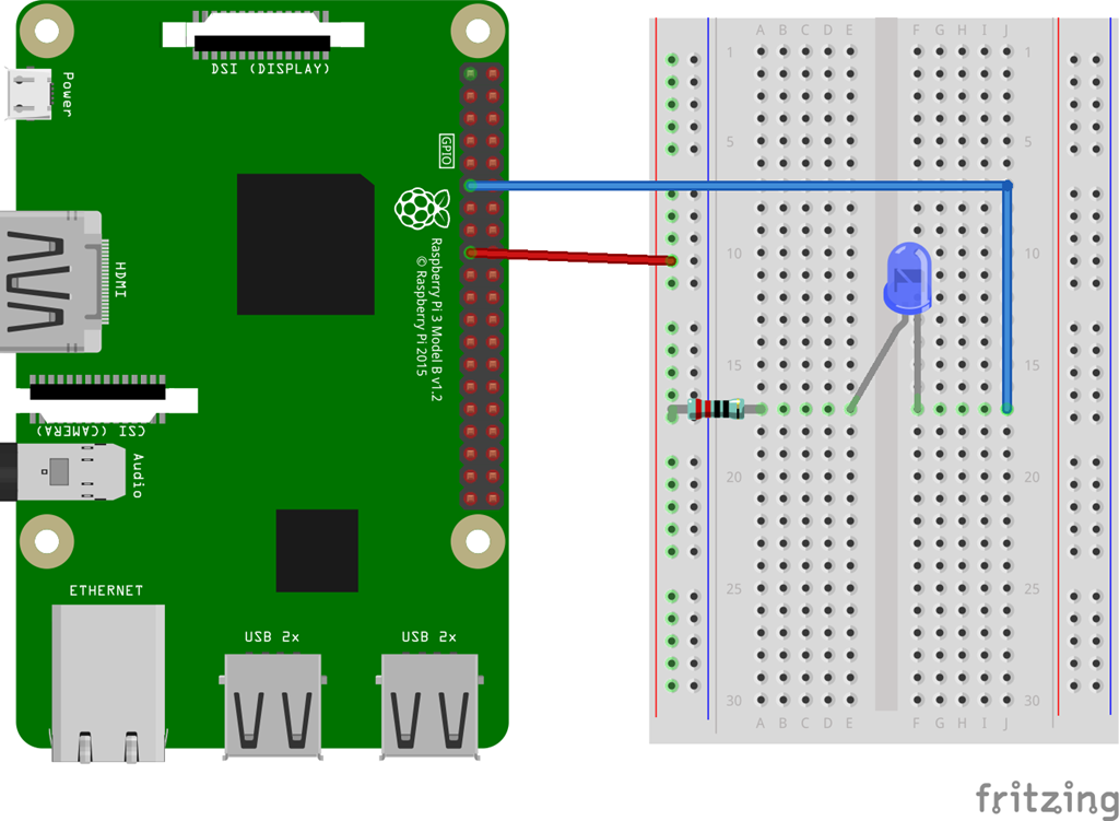
Next, wire up a simple circuit. You will need a breadboard, an LED, a 220 Ohm resistor and some link leads:
- Connect 3V3 to the positive rail of the breadboard
- Connect GPIO 17 (physical pin 11) to the negative lead of the LED
- Use the 220 Ohm resistor to connect the positive rail to the positive lead of the LED.
-
To test the app, enter the following command:
dotnet runAfter a few moments of compilation, the app will run and you should see two things:
-
The LED flashing
-
A console log:
>LED1 on for 1000ms
LED1 off for 200ms
LED1 on for 1000ms
LED1 off for 200ms
LED1 on for 1000ms
LED1 off for 200ms
LED1 on for 1000ms
LED1 off for 200ms
LED1 on for 1000ms
LED1 off for 200ms
LED1 on for 1000ms
-
-
Hit CTRL-C to stop the app.
Implementing a Binary Display
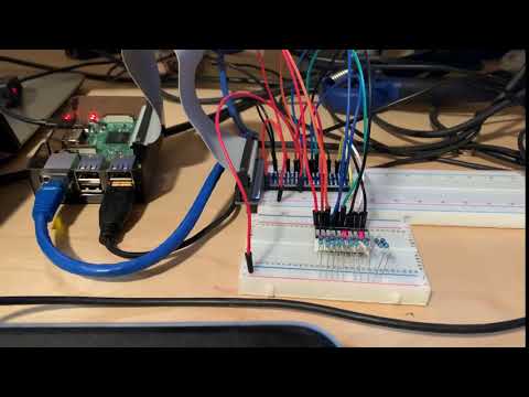
Next we will extend the sample above by adding more LEDs which we will use to display binary numbers. You can either connect individual LEDs, or an LED Bar Graph component (one is included in the kit I linked to above):
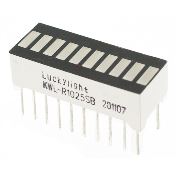
Note: It is hard to determine which way round to fit these, you may have to rotate it if none of the LEDs come on...
-
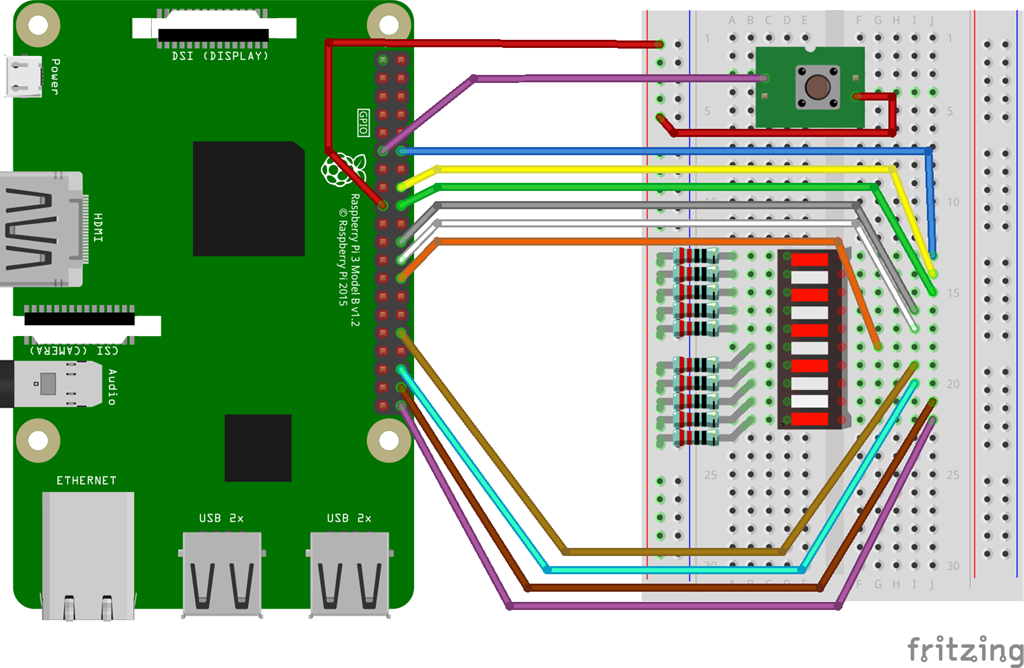
Update the breadboard wiring as follows:
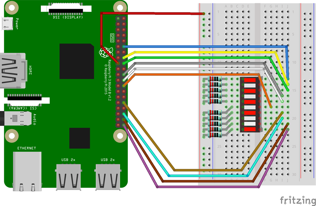
Note that the resistors supply power to one side of the LEDs, and pulling a pin low causes current to flow, illuminating the LEDs.
Also, I have chosen pins based upon wiring convenience, rather than following an form of numbering convention - to be honest, the pin layout of the GPIO bus on the PI only makes sense based upon the convenience of the manufacturer.
Anyway, the pins I used are:
Physical Pin GPIO Used Display Bit 12 GPIO 18 X 9 14 GND 16 GPIO 23 X 8 18 GPIO 24 X 7 20 GND 22 GPIO 25 X 6 24 GPIO 8 X 5 26 GPIO 7 X 4 28 Reserved 30 GND 32 GPIO 12 X 3 34 GND 36 GPIO 16 X 2 38 GPIO 20 X 1 40 GPIO 21 X 0 -
Once you have completed the circuit, return to Visual Studio Code.
-
Replace the contents of the Program.cs file with the following:
using System;
using System.Device.Gpio;
using System.Threading;
using System.Threading.Tasks;

namespace SimpleFlasher {
    class Program {

        // a list of all the pins used to display the value
        // pins are listed in the most significant bit order
        // i.e. pin 18 represents the highest value
        static int[] _pins = { 18, 23, 24, 25, 8, 7, 12, 16, 20, 21 };
        static GpioController _controller = new GpioController ();

        static void Main (string[] args)
        {
            // Set all the pins to output mode and
            // ensure all the LEDs are off
            foreach (var pin in _pins)
            {
                _controller.OpenPin (pin, PinMode.Output);
                _controller.Write (pin, PinValue.High);
            }

            // play around with this value.
            //   0 will result in a virtually instant count
            //  10 looks cool
            int countDelay = 100;
            int value = 0;

            // 1 << 2 is a bit shift operation
            // 1 << 2 == 1 * 2 * 2 == 4
            // so 1 << _pins.Length represents the max number we can display + 1
            while (value < (1<<_pins.Length))
            {
                Console.WriteLine(value);
                DisplayValue(value++);
                Thread.Sleep (countDelay);
            }
        }

        static void DisplayValue(int value)
        {
            var currentBit = _pins.Length;
            while(currentBit > 0)
            {
                // _pins[10-currentBit] accesses the pin number for the current bit
                // (value & 1< 0 ? PinValue.Low : PinValue.High);
                currentBit--;
            }
        }
    }
}
The code is explained with inline comments.
-
Compile and run the code with the following command:
dotnet run
Once complete and running, the LEDs should display an incrementing value in binary.
Note: If the LEDs don't light up, turn them around - it is easy to put them in the wrong way.
 Click the image to view a video
OK - so now we have worked out how to flash some LEDs by using some pins in output mode. Let's add a switch to our circuit and use it to reset count.
Reading Input
Now we are going to add a switch to the circuit and check to see if the switch is pressed each time we loop.
-
Add the following variable above the
Mainmethod:// The pin we will use to reset the count static int _switchPin = 17; -
Replace the
Mainmethod with:static void Main (string[] args) { // Set all the pins to output mode and // ensure all the LEDs are off foreach (var pin in _pins) { _controller.OpenPin (pin, PinMode.Output); _controller.Write (pin, PinValue.High); } // Set the pin mode. We are using InputPullDOwn which uses a pulldown resistor to // ensure the input reads Low until an external switch sets it high, // We could have used InputPullUp if we wanted it to read High until it was pulled down Low. // If we just used Input, the value on the pin would wander between High and Low... not very useful in this situation. _controller.OpenPin(_switchPin, PinMode.InputPullDown); // play around with this value. // 0 will result in a virtually instant count // 10 looks cool int countDelay = 100; int value = 0; // We'll loop forever now - CTRL + C to exit while (true) { Console.WriteLine(value); // _pins[10-currentBit] accesses the pin number for the current bit // (value & 1<<currentBit) performs a bitwise AND operation to check if the bit is set in the value // If the bit is set, the ternary expression sets the PinValue.Low (on) or if not, PinValue.High (off) DisplayValue(value); // don't keep incrementing the value once we hit max if (value < (1<<(_pins.Length+1))-1) { value++; } // Check input value each time we loop if (_controller.Read(_switchPin) == PinValue.High) { // button pressed value = 0; } Thread.Sleep (countDelay); } }As usual, the code is heavily commented to explain what is going on. We now have an infinite loop and we poll the status of the input pin each loop to determine if the pin value is high - if so, we reset the value to zero.
-
Let's update the circuit to include a switch connected between 3.3v and GPIO 17.
-
Compile and run the code with the following command:
dotnet runYou should now see the LEDs display an incrementing value in binary - if you leave it running long enough, it will reach 2047 and all LEDs will be lit. Pressing the switch will raise GPIO 17 high, which will cause the value to be reset to zero. Once you release the switch, the count will begin again.
So in this article we explored using the the GPIO in both output and input modes. In the next article I will start to explore I2C.